vision
Child rooms panel
Main objectives
- Add LED strip to childs bed with WLED driven controller
- Design, 3d print, assemble the box
- Use ESP32 with ESPHome firmware
- Configure the buttons to control WLED LED strip
- Document it well and share it
Design requirements
- DIY!
- OTA upgrades.
- Repairable
- A variety of different type/color arcade buttons
- A box is running on a rechargable battery
Goals that define basic success
A child is able to control bed LEDs with his panel
- Turn on/off
- Change colors
- Cycle through effects
- Set a timer(might be a bad idea)
End goal of (un)achievable completion
Use buttons for Home Assistant exposed entities
- Roller shutters
- Sonos speakers
- etc.
the-story
Inspiration
Not much of a story here. I visited a friend and saw that he had built a control box for his kid - just a few buttons to turn an IKEA LED strip on and off. As the saying goes: good artists copy, great artists steal (and call themselves artists).
Motivation
I decided to pick on a challenge. Like some of my previous projects, this one touches on several of my hobbies: electronics, CAD modeling, and 3D printing. Seemed like the perfect excuse to dive in.
Sketching It Out
After thinking it through, here’s what I came up with:
- An RGB LED strip going around the bed - white LEDs felt too boring.
- A cheap OEM 12V 5A power supply and a Gledopto ESP32-based LED controller with a built-in mic.
- A control box mounted next to the bunk bed. Since there wasn't much space to secure it, I decided to hang it.
- An ESP32 DevKit MCU running ESPHome firmware.
- A rechargeable 18650 battery - because it's for a 4yo (ab)user, and I’m not swapping AAs every day.
- A USB-C port for charging and power.
Shopping List
Tools
- Many. All kinds of 🌚
Bed LEDs
- 3 meters of SK6812 RGBW 60LED/m (widely available on Amazon/Aliexpress)
- Any 12V 3A+ DC power supply
- Gledopto GL-C-010WL
Control Box Internals
- Arcade buttons (lots of options online and locally)
- ESP32 MCU (ESPHome supports a wide range - from ESP8266 to newer ones)
- 18650 lithium rechargeable battery
- USB-C battery charging module
Control Box Case (Optional)
- 3D printer
- Filament
- CAD modeling skills
- Heat inserts, standoffs, M3 screws
A custom case is nice, but you could also reuse a tin cookie box, a cardboard box (for prototyping), or put together something from wood..
The Process / Pr(👹)ss
After ordering a bunch of arcade buttons, I let my son pick the ones he wanted. I laid them out on a cardboard box to visualize the layout and spot early design issues before diving into CAD.
My CAD Workflow
- Sketch the shape in Plasticity.
- Transfer to Blender using the Blender Bridge add-on.
- Clean up the messy mesh and export as
.stl. - Slice and send to the 3D printer.
Design Considerations
One key requirement: hinges. Since the box is hanging and will eventually need maintenance (button/MCU replacements), I wanted a hinged lid that opens without pulling on wires and hangs instead of having to put it away somewhere.
I used brass heat inserts to allow for repeated assembly/disassembly with proper screw tension.
The case had to be split into parts due to 3D printer bed size limitations. I used a dovetail joint and internal screws to hold it together.
Once printed and assembled, I mounted the battery, charger module, MCU, and buttons, and wired it all up.
The Fun Bugs
Naturally, a few issues popped up - mainly hinge design flaws. Some broke easily, others didn’t open smoothly. Hopefully, inspiration will strike before the next build.
Wiring a Push-to-Light Button
I wanted the button's built-in LED to light up only while the button is pressed. A small challenge, but a fun one.
Thankfully, I had a transistor kit that had PNP transistor(BC557). Here's how I wired it:
- Button LED positive → 5V
- Button LED negative → transistor collector
- Transistor emitter → GND
- Transistor base → 1kΩ resistor →
- MCU pin (pulled HIGH by default)
- Push button pin #1
- Push button pin #2 → GND
How it works: When the button is pressed, the MCU pin is pulled LOW, allowing current from the collector to the emitter and lighting the LED. When released, the MCU pin goes HIGH and cuts off the ground path, turning the LED off.
Final Wiring
- All buttons: pin #1 → GND
- All buttons: pin #2 → dedicated MCU pins
Since ESPHome uses YAML config, I declared pins directly in the config file using their docs as reference.
Wi-Fi Delay UX Fix
When the box powers on, it takes a few seconds to connect to Wi-Fi - which is way too long for a kid's attention span. To handle this, I added another LED next to the power switch, wired it to the MCU, and programmed it to light up only after Wi-Fi connects. My son now knows to press buttons only when that LED is on.
And that’s it. A fun weekend project that mixes electronics, CAD, 3D printing - and gave me a good excuse to catch up on some podcasts.
gallery
Project Gallery
A visual walkthrough of the RGB LED bed controller project.
🌈 Bed LEDs In Action
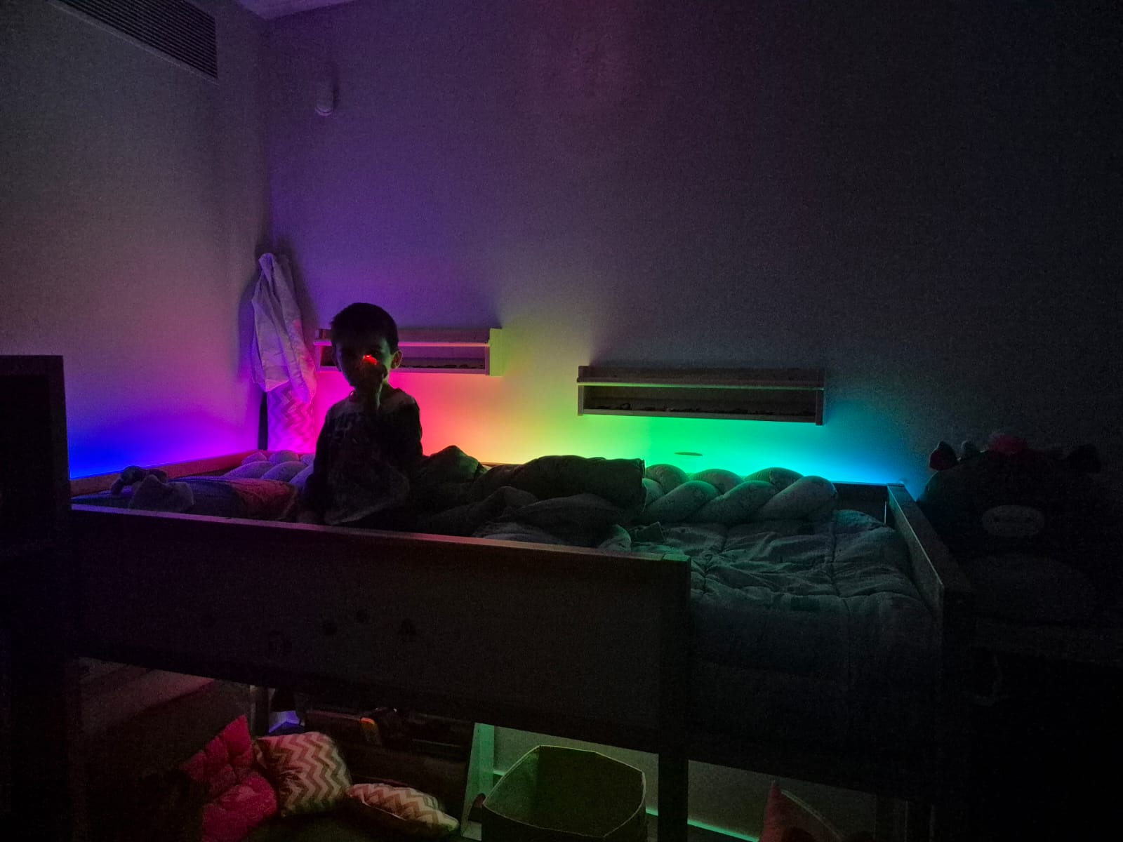 The SK6812 RGBW LED strip installed around the bed frame.
🧪 Early Prototype
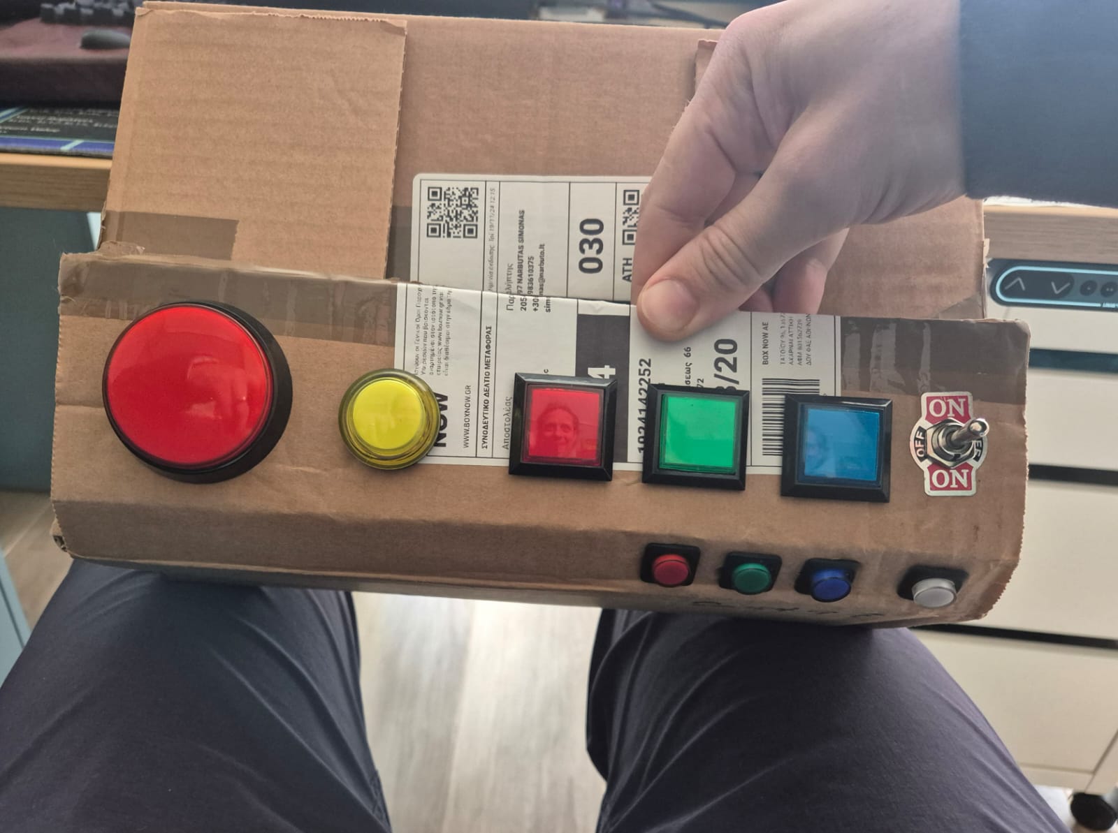 Laying out arcade buttons on a cardboard box to validate the design and spot early issues before CAD modeling.
🧠 Internals
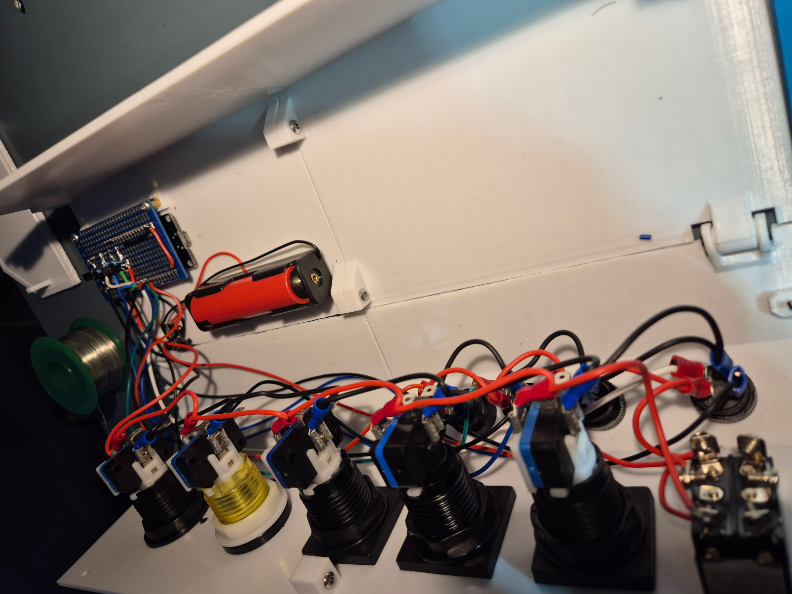 Shows the USB-C charging module, 18650 battery, PCB prototyping board, detachable wires. You can see how the case is pulled together.
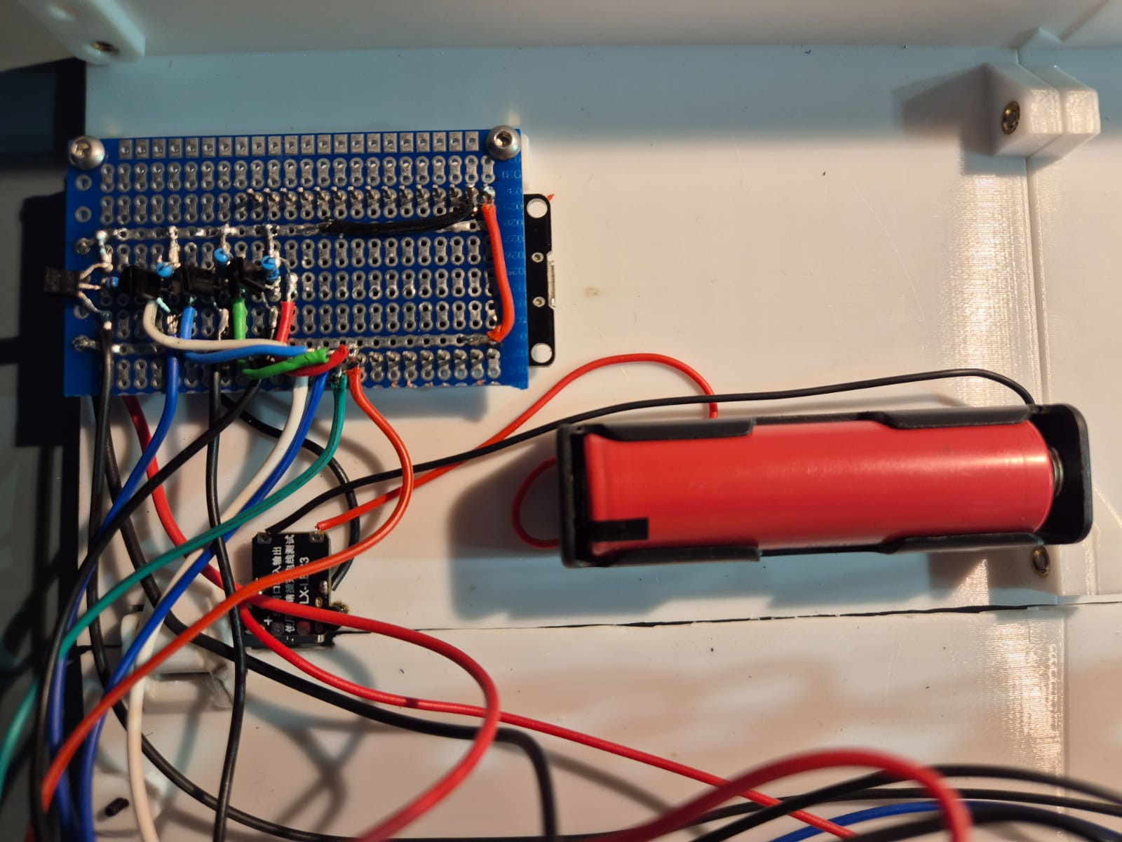 Early shot of the MCU and transistor and charging module wiring. Hard to make out details from the picture but it gives general idea.
📦 Mounted Control Box
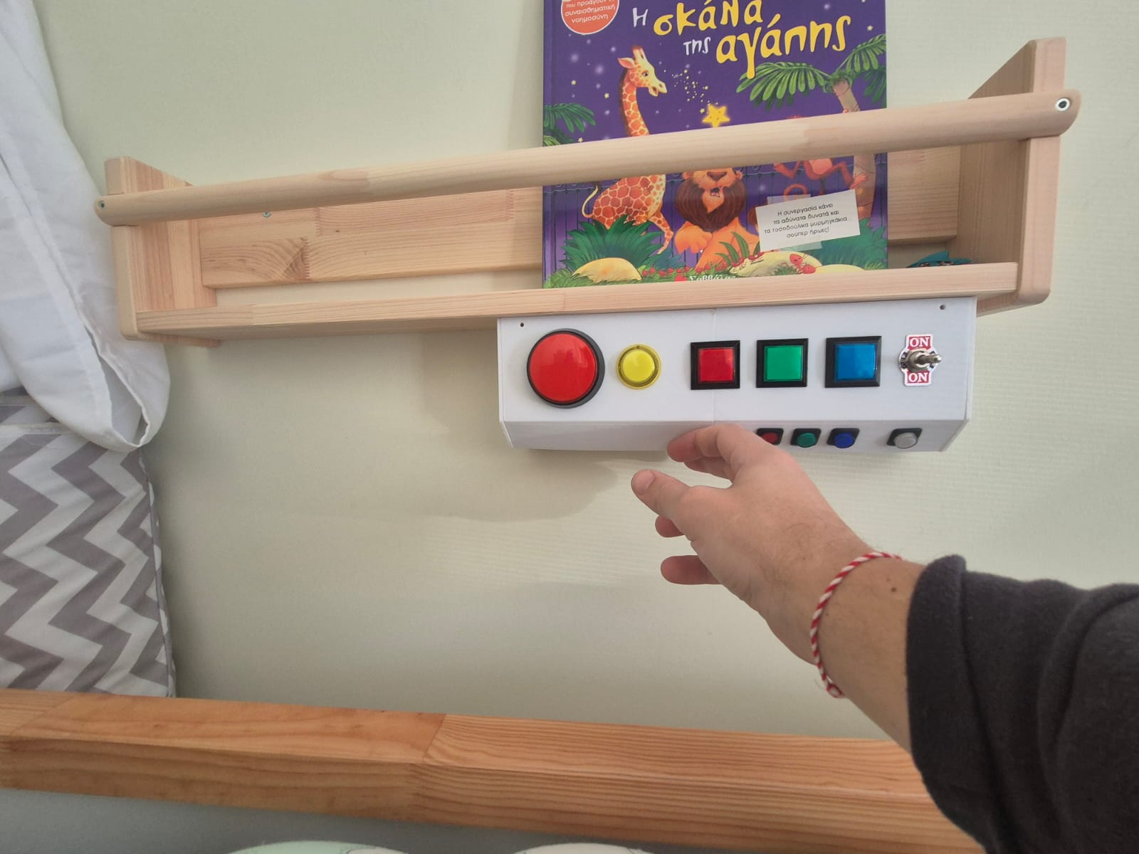 The final control box mounted next to the bunk bed. Hinges are at the bottom back, so whe lid will be hanging when pulled down by gravity when opened.
✅ Finished Control Box
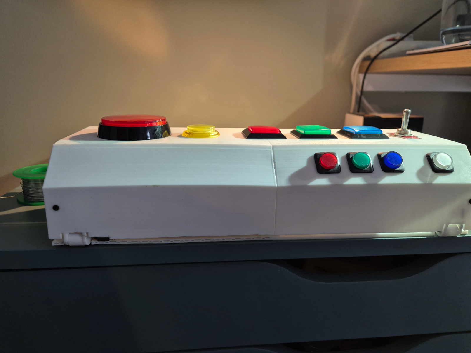 Side view of the case. USB-C charging port. Hinge design flaws. Wall had to be shaved to allow hinges to open. Front needed supports in the middle when printing as the walls slightly arched in the middle.
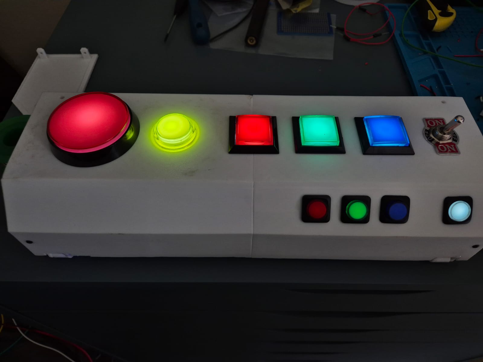 The completed box - ready for some serious 4yo abuse.